The Elegant Logic of Bernoulli's Principle
The study of fluid dynamics is anchored by a singular, elegant realization: the energy within a flowing liquid or gas remains constant along its path, merely shifting its form between pressure,...
The study of fluid dynamics is anchored by a singular, elegant realization: the energy within a flowing liquid or gas remains constant along its path, merely shifting its form between pressure, velocity, and elevation. This concept, known as Bernoulli's principle, serves as the cornerstone of modern aerodynamics, hydraulics, and thermal engineering. Formulated by the Swiss mathematician Daniel Bernoulli in his 1738 masterpiece Hydrodynamica, the principle describes the seemingly counterintuitive behavior of fluids where an increase in speed occurs simultaneously with a decrease in static pressure. To understand this relationship is to understand how massive aircraft stay aloft, how fuel atomizes in an engine, and how blood flows through the human circulatory system. By treating a fluid as a continuous medium governed by the laws of classical mechanics, we can derive a mathematical framework that bridges the gap between abstract physics and practical engineering.
Foundations of Fluid Mechanics Basics
To grasp the logic of Bernoulli's principle, one must first establish the parameters of an ideal fluid. In the complex reality of nature, fluids exhibit internal friction and can be compressed, but for the sake of foundational physics, we assume the fluid is incompressible and non-viscous. Incompressibility implies that the density of the fluid remains constant regardless of the pressure applied, a condition that holds true for most liquids and for gases moving at low speeds. Non-viscosity, or inviscid flow, assumes that there is no internal "stickiness" or friction between layers of the fluid, allowing us to ignore energy loss to heat. These simplifications allow engineers to focus on the interplay of mechanical energies without the chaotic interference of thermal dissipation.
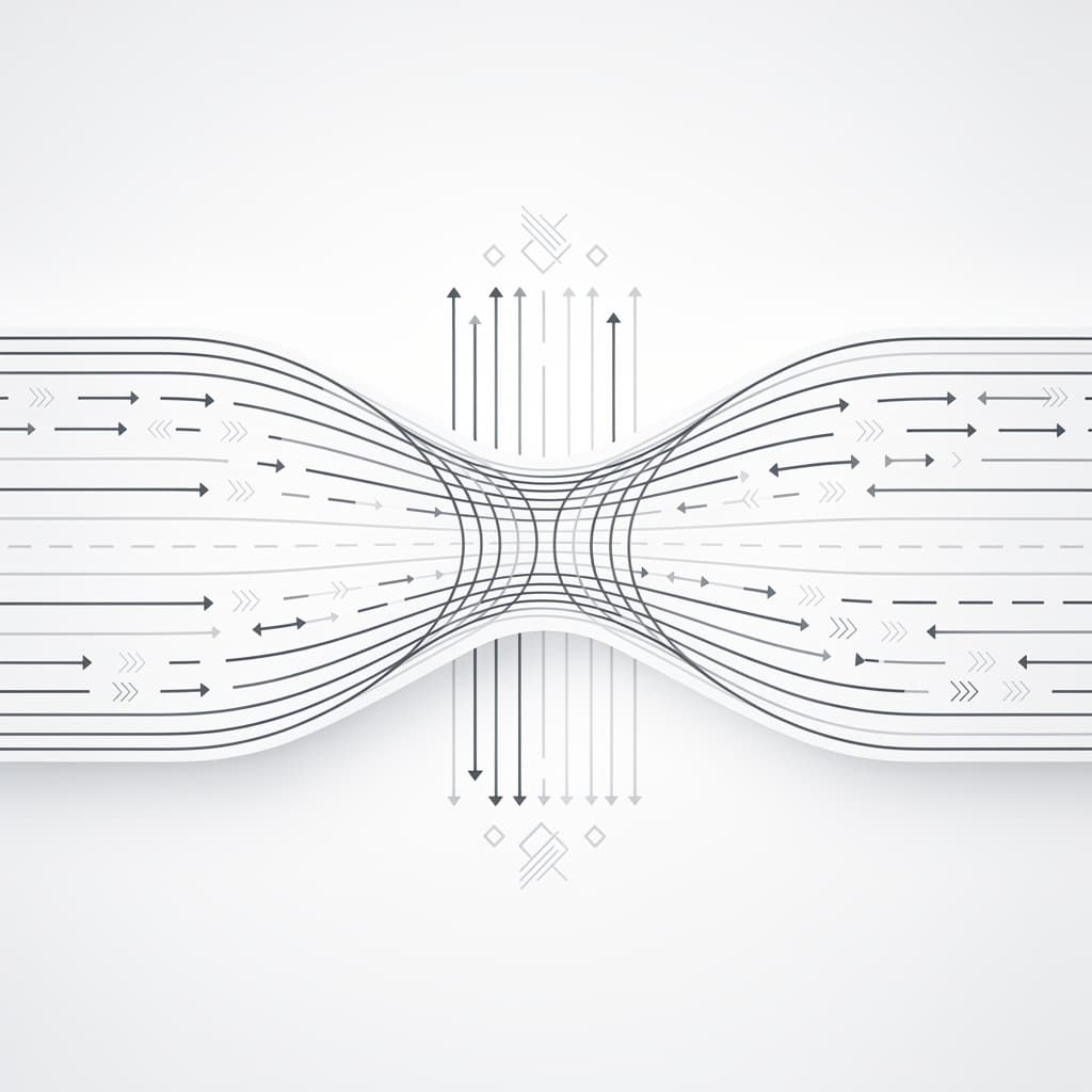
The visualization of fluid motion is achieved through the concept of streamlines and laminar motion. A streamline is an imaginary line within the flow where the tangent at any point indicates the velocity vector of the fluid particle at that location. When a fluid moves in smooth, parallel layers without mixing or cross-currents, it is described as laminar flow, a steady-state condition where the fluid velocity at any fixed point remains constant over time. In this state, streamlines never cross; if they did, a particle at the intersection would have two different velocities simultaneously, which is a physical impossibility. This steady-state framework is essential for Bernoulli’s logic, as it ensures that the energy measured at one point in the stream can be directly compared to the energy at another point further downstream.
At its heart, fluid mechanics is a manifestation of the conservation of energy applied to continuous media. In a closed system where no energy is added by pumps or removed by friction, the total mechanical energy must remain constant along a streamline. This energy exists in three primary forms: the potential energy of the fluid's pressure, the kinetic energy of its motion, and the gravitational potential energy of its height. When a fluid particle accelerates, it must gain kinetic energy; according to the law of conservation, this energy cannot appear from nowhere and must be "borrowed" from its pressure or its elevation. This fundamental trade-off is the governing logic that allows us to predict fluid behavior in everything from simple plumbing to complex industrial turbines.
The Mathematical Foundation: Bernoulli's Equation
The formal expression of this energy conservation is known as Bernoulli's equation. It is derived by applying the work-energy theorem to a small volume of fluid moving along a streamline. If we consider a segment of fluid moving through a pipe of varying cross-sections and heights, the work done on the fluid by the surrounding pressure must equal the change in its kinetic and potential energy. By integrating the forces acting upon this fluid element along its path of motion, we arrive at a constant sum that defines the fluid's state at any given point. The equation provides a quantitative map for engineers to calculate unknown variables like velocity or pressure when the other conditions of the flow are known.
The standard form of Bernoulli's equation is typically written as follows: $$P + \frac{1}{2} \rho v^2 + \rho gh = \text{constant}$$ In this expression, $P$ represents the static pressure, which is the actual pressure of the fluid exerted in all directions. The second term, $\frac{1}{2} \rho v^2$, represents the dynamic pressure, which accounts for the kinetic energy density of the fluid moving at velocity $v$ with a density of $\rho$. The third term, $\rho gh$, accounts for the hydrostatic pressure or the potential energy per unit volume due to gravity, where $g$ is the acceleration due to gravity and $h$ is the elevation relative to a reference plane. Together, these terms represent the total pressure or total head of the system, which remains invariant along the streamline.
Integrating gravitational potential energy into the equation is vital for understanding vertical fluid transport, such as water rising through a skyscraper's plumbing or the flow of a mountain stream. When the height $h$ increases, the potential energy $\rho gh$ increases, requiring a compensatory decrease in either the static pressure or the velocity to maintain the constant sum. However, in many aerodynamic applications where the change in height is negligible, the $\rho gh$ term is often omitted, simplifying the relationship to a direct trade-off between pressure and velocity. This simplified version is what most people refer to when discussing the pressure and velocity relationship in high-speed airflows or horizontal pipe systems.
Pressure and Velocity Relationship Mechanics
The most famous takeaway from Bernoulli's principle is the inverse correlation principle: as the velocity of a fluid increases, its static pressure decreases. This occurs because the total energy per unit volume is fixed; if a greater portion of that energy is dedicated to the motion of the particles (kinetic energy), less energy is available to be exerted as outward force (pressure). It is important to realize that "pressure" in this context refers to the internal pressure within the fluid stream, not the force the fluid would exert if it crashed into a wall. The reduction in pressure is a direct consequence of the fluid doing work on itself to accelerate into a region of higher speed.
The concept of kinetic energy density helps us visualize why this happens in narrow channels or constricted areas. When a fluid enters a narrower section of a pipe, it must speed up to ensure that the same mass of fluid passes through the constriction in the same amount of time—a requirement known as the continuity equation ($A_1v_1 = A_2v_2$). As the fluid speeds up, its kinetic energy per unit volume ($\frac{1}{2} \rho v^2$) rises sharply. Since the fluid is not being powered by an external motor in this segment, that increase in kinetic energy must come from the internal energy of the fluid itself, leading to a measurable drop in static pressure in the narrow zone. This drop is not just a theoretical curiosity but a powerful force that can be used to suction other fluids or measure flow rates.
The mechanics of this relationship are deeply rooted in the work-energy theorem in hydrodynamics. For a fluid to accelerate, there must be a net force acting on it in the direction of motion. In a horizontal pipe, this force can only come from a difference in pressure; specifically, the pressure behind the fluid must be higher than the pressure in front of it. Therefore, a region of high velocity must naturally be a region of lower pressure compared to the slower-moving fluid behind it. This pressure gradient is the "engine" that drives the fluid's acceleration, ensuring that the transition from slow to fast flow is physically consistent with Newton’s Second Law of Motion.
Understanding the Venturi Effect
The Venturi effect is perhaps the most practical and widely recognized manifestation of Bernoulli's principle in engineering. It describes the reduction in fluid pressure that results when a fluid flows through a constricted section (or "throat") of a pipe. Named after the Italian physicist Giovanni Battista Venturi, this effect demonstrates that by simply changing the geometry of a conduit, one can manipulate the pressure and velocity of the flow without any moving parts. As the fluid enters the constriction, its velocity reaches a maximum and its pressure reaches a minimum, creating a localized vacuum-like state that can be utilized for various industrial purposes.
One of the primary applications of this effect is in the design of manometers and Venturi flow meters. By placing a pressure gauge at the wide section of a pipe and another at the narrow throat, engineers can measure the pressure difference ($\Delta P$) between the two points. Using Bernoulli's equation, this pressure difference can be used to calculate the exact velocity and volume flow rate of the fluid. Because these meters have no moving parts and offer predictable performance, they are standard equipment in large-scale water treatment plants, oil pipelines, and chemical processing facilities where reliability and low maintenance are paramount.
Industrial use cases for the Venturi effect extend into the realm of fluid mixing and suction. In a device known as an aspirator or an ejector, a high-speed fluid jet passes through a Venturi throat, creating a low-pressure zone that draws in a secondary fluid or gas through a side inlet. This principle is used in medical suction pumps, industrial vacuum systems, and even in large-scale steam injectors for locomotives. The elegance of the design lies in its simplicity; by harnessing the inherent fluid mechanics basics of the medium itself, engineers can achieve complex mechanical tasks like siphoning or mixing with incredible efficiency and zero electrical input.
Real-World Bernoulli's Principle Examples
In the field of aerodynamics, Bernoulli's principle is frequently cited as a primary factor in wing lift generation. As an airplane wing (airfoil) moves through the air, its shape is designed to force air to travel faster over the curved top surface than across the flatter bottom surface. According to the principle, the faster-moving air on top exerts less downward pressure than the slower-moving air on the bottom exerts upward. This pressure differential results in a net upward force known as lift. While modern aerodynamics also incorporates Newton’s Third Law (downwash and flow turning), the pressure-velocity relationship remains a critical component of wing design and performance calculations.
Another classic example is found in the mechanics of atomizers and carburetors. In a simple perfume spray bottle, a squeeze of the bulb sends a high-speed stream of air across the top of a tube submerged in the liquid. The high velocity of the air creates a low-pressure zone at the top of the tube, causing the atmospheric pressure acting on the surface of the liquid in the bottle to push the liquid up the tube. Once the liquid reaches the air stream, it is broken into fine droplets and carried away as a mist. Mechanical carburetors in older internal combustion engines operate on the same principle, using a Venturi throat to draw fuel into the air intake stream in precise proportions.
The Magnus effect in sports ballistics provides a dynamic example of these principles in action. When a soccer ball, tennis ball, or baseball is thrown with spin, it drags a thin layer of air around with it. On one side of the ball, the spin moves in the same direction as the oncoming air, increasing the local air velocity; on the opposite side, the spin moves against the air, decreasing the velocity. The resulting pressure imbalance—lower pressure on the high-velocity side and higher pressure on the low-velocity side—pushes the ball toward the low-pressure side, causing it to curve in flight. Athletes instinctively master these fluid mechanics basics to manipulate the trajectory of the ball, turning the air itself into a tool for strategic advantage.
Beyond Ideal Fluids: Real-World Constraints
While Bernoulli's principle provides a powerful foundation, it is vital to acknowledge its limitations when dealing with real-world fluids. The most significant divergence from the ideal model is the impact of viscosity and friction. In any real pipe or channel, the fluid molecules rubbing against the walls and against each other create shear stress, which converts mechanical energy into heat. This "head loss" means that the total energy along a streamline actually decreases over distance. Engineers must use the Darcy-Weisbach equation or the Hagen-Poiseuille law to account for these losses, ensuring that pumps and systems are sized correctly to overcome the drag inherent in viscous flow.
Energy loss is particularly pronounced in turbulent systems. When fluid velocity increases beyond a certain threshold—defined by the Reynolds number—the smooth, predictable streamlines of laminar flow break down into chaotic eddies and vortices. Turbulence drastically increases the rate of energy dissipation, rendering the basic Bernoulli's equation insufficient for precise calculations. In these cases, the principle still describes the general trend of pressure and velocity, but empirical "loss coefficients" must be added to the equation to maintain accuracy. Understanding where laminar flow ends and turbulence begins is a critical skill for engineers designing high-speed transport systems or mixing tanks.
Finally, we must consider the application limits in compressible media, such as air at high speeds. Bernoulli’s standard equation assumes a constant density ($\rho$), but as air approaches the speed of sound (Mach 1), its density changes significantly in response to pressure changes. For high-speed aerodynamics, a compressible version of the equation must be used, which incorporates thermodynamic variables like temperature and the ratio of specific heats. Despite these complexities, the core "elegant logic" of the principle remains: energy is conserved, and the movement of a fluid is always a delicate balance between its internal pressure and its external motion. By mastering this balance, we continue to push the boundaries of what is possible in the physical world.
References
- Bernoulli, D., "Hydrodynamica, sive de viribus et motibus fluidorum commentarii", Johannis Reinholdi Dulseckeri, 1738.
- White, F. M., "Fluid Mechanics", McGraw-Hill Education, 8th Edition, 2015.
- Anderson, J. D., "Fundamentals of Aerodynamics", McGraw-Hill Education, 2016.
- Munson, B. R., Okiishi, T. H., Huebsch, W. W., & Rothmayer, A. P., "Fluid Mechanics", Wiley, 7th Edition, 2012.
Recommended Readings
- The Feynman Lectures on Physics, Vol. 2 by Richard Feynman — Specifically the chapters on the physics of continuous media, which offer a deep intuitive dive into fluid flow and conservation laws.
- Flow by Philip Ball — A captivating exploration of how fluid dynamics shapes the natural world, from the patterns in clouds to the branching of rivers.
- An Album of Fluid Motion by Milton Van Dyke — A visual masterpiece containing hundreds of photographs of streamlines, turbulence, and the Venturi effect that bring the math of Bernoulli to life.